
Deutsche Version weiter unten, hier klicken
One thing I learned while building my previous segmented layout—and also from software design at work—is the value of prototyping. In simple terms, this means creating a draft or test model first and checking whether it actually fits its intended purpose. Something that looks perfectly fine on paper may still need adjustments once you start turning it into a physical model. I am a very visual person, so this approach helps me a lot.
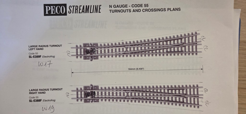
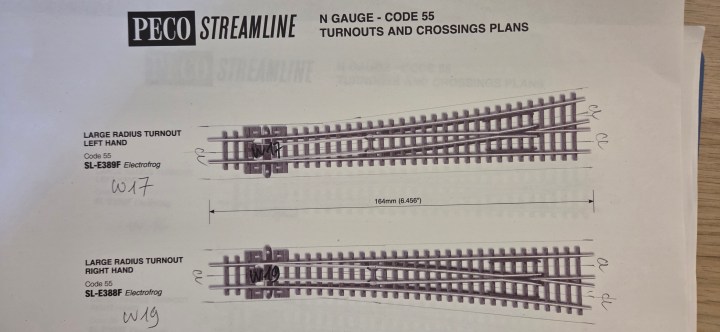
If you are using Peco turnouts like I am, I highly recommend printing out their turnout templates. For the Effem module, I will be using a total of six Peco Code 55 large Electrofrog turnouts for the mainline and two medium Unifrog turnouts. I therefore printed the turnout templates at 1:1 scale, marked the track centre lines (CL) and the boundaries of the embankment, and identified the position of each turnout on the Effem module.
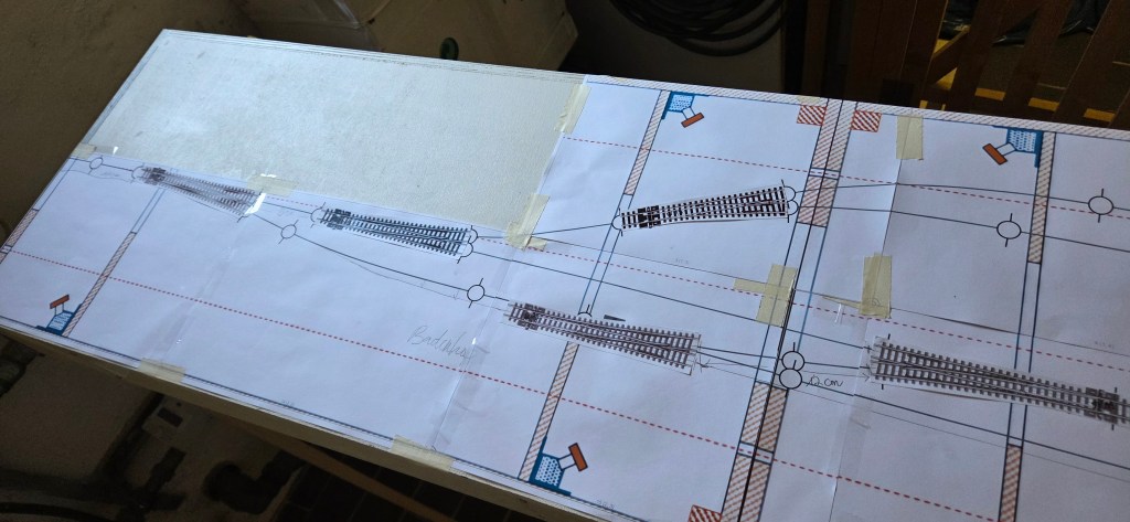
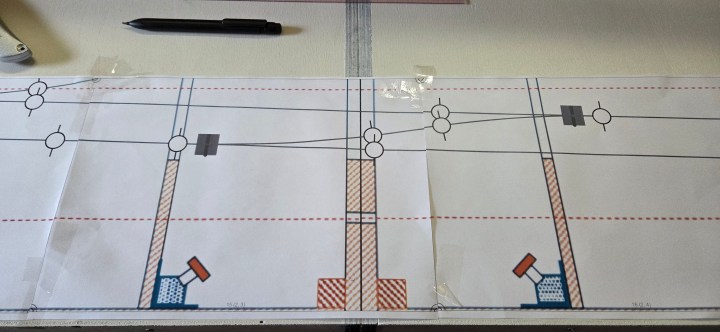
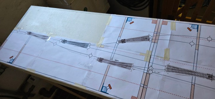
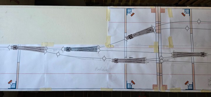
I then placed the paper turnouts on top of the AnyRail track plan, which I had already printed at 1:1 scale and fixed to the baseboard. This is where the advantage of using paper turnouts became immediately obvious: I could move them around, adjust their positions and see how they actually fitted the track plan on the physical module.
And straight away, I found the first problem.
The bottom turnout was positioned across the joint between two segments. That would obviously create problems later. I had not noticed this when drawing the track plan in AnyRail, but with the 1:1 plan laid out on the actual baseboard, the problem was impossible to miss. More importantly, I could now correct it before laying a single piece of track or installing a turnout.
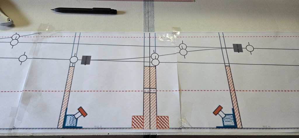
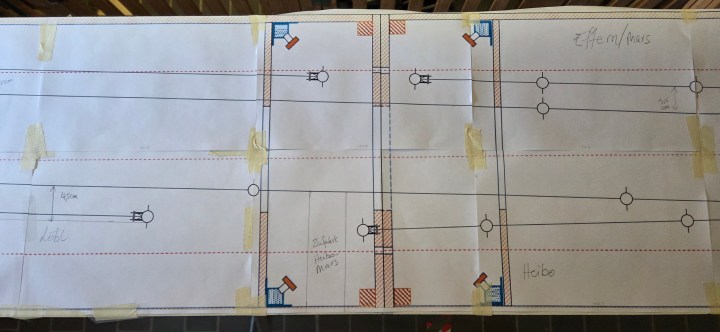
Then I spotted another issue. Turnouts 16 and 17 in the Badenhop/Löbl area were too close to the module edges. The two turnout positions were originally 350 mm apart. I increased this distance to 450 mm and repositioned both turnouts so that they aligned better. There is now a 120 mm section of straight track between the two turnouts, which looks much more convincing.
Update: At this stage of the build, I still regarded this arrangement as being closer to the prototype. Later research into photographs and track plans showed that the Badenhop/Löbl arrangement changed over time and that the runaround represented on my module does not correspond exactly to the situation in my core 1979–1989 period. I have nevertheless retained it as a deliberate prototype-freelance compromise because it gives the module considerably more operational flexibility. I will return to this in the later operating trials.
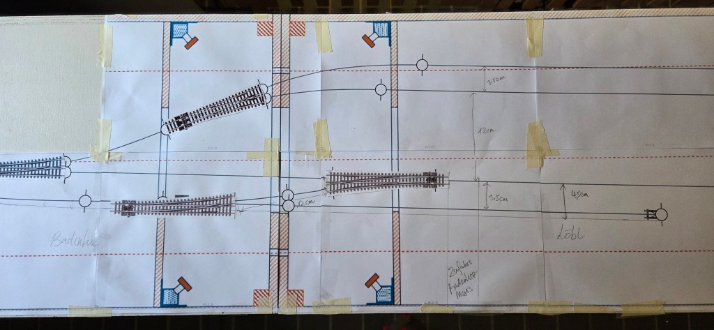
At the other end, turnout 14 in the Effem siding also needed to move a few millimetres away from the module edge. Apart from these adjustments, all the other turnouts fitted exactly where they were supposed to.
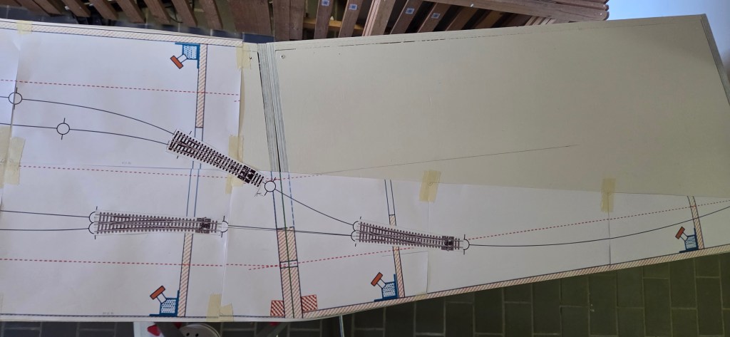
The paper templates are useful for more than just getting a visual impression of the complete track arrangement on the Effem module. They also allow me to check what is happening underneath the baseboard. I can see whether a turnout interferes with cross-members or other parts of the module frame and determine the exact positions of the throw bar and frog. This is particularly important when planning the wiring and positioning underboard turnout mechanisms such as MTB switch motors or manual turnout levers.
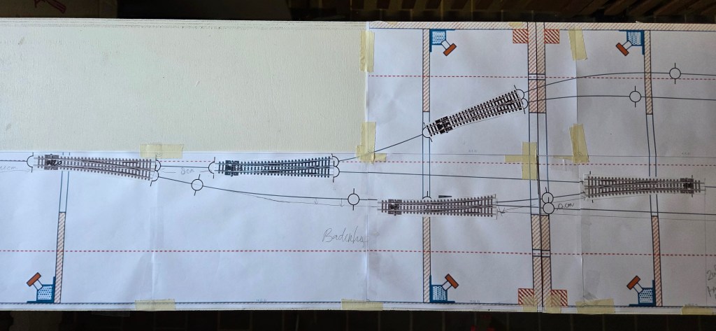
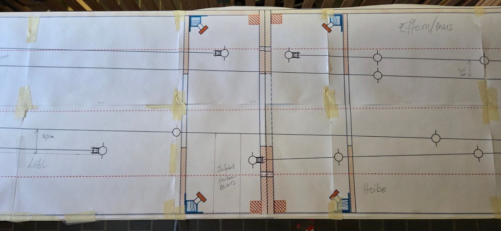
Because I am using flex track, getting the turnout positions right is the most important part of the track geometry. Once the turnouts are in the correct positions, the flex track simply connects them together.
This little exercise once again confirmed why I like prototyping before committing to the final construction. AnyRail gives me the plan, but laying everything out at 1:1 scale on the actual module tells me whether that plan really works.
DEUTSCHE VERSION
Verden-Walsroder Eisenbahn (VWE): Mit Papierweichen zum Praxistest
Eine Sache habe ich aus meinem bisherigen Segmentbau gelernt – und interessanterweise auch aus der Softwareentwicklung bei der Arbeit: Prototyping lohnt sich. Vereinfacht gesagt erstellt man zunächst einen Entwurf oder ein Versuchsmodell und prüft, ob das Ganze in der Praxis tatsächlich so funktioniert wie gedacht. Was auf dem Papier perfekt aussieht, muss beim Übertragen in die Realität oft noch angepasst werden. Ich bin ein sehr visueller Mensch, deshalb hilft mir diese Methode enorm.
Wenn ihr wie ich Peco-Weichen verwendet, kann ich nur empfehlen, die entsprechenden Weichenschablonen auszudrucken. Für das Modul Effem werde ich insgesamt sechs große Peco-Code-55-Electrofrog-Weichen für das Hauptgleis sowie zwei mittlere Unifrog-Weichen verwenden. Also habe ich die Weichenschablonen im Maßstab 1:1 ausgedruckt, die Gleismitten (CL) sowie die Begrenzungen des Bahndamms eingezeichnet und die jeweilige Position der Weichen auf dem Modul Effem markiert.
Anschließend legte ich die Papierweichen auf den ebenfalls im Maßstab 1:1 ausgedruckten AnyRail-Gleisplan, den ich bereits auf der Grundplatte fixiert hatte. Genau hier zeigte sich sofort der Vorteil der Papierweichen: Ich konnte sie verschieben, ihre Lage korrigieren und direkt auf dem Modul sehen, wie die geplante Gleisgeometrie tatsächlich wirkt.
Und prompt entdeckte ich das erste Problem.
Die untere Weiche lag genau über der Trennstelle zwischen zwei Segmenten. Das hätte später natürlich Probleme verursacht. Beim Zeichnen des Gleisplans in AnyRail war mir das überhaupt nicht aufgefallen. Mit dem 1:1-Ausdruck auf der tatsächlichen Grundplatte war es dagegen sofort offensichtlich. Vor allem kann ich das Problem jetzt noch korrigieren, bevor auch nur ein einziges Gleis oder eine Weiche fest verlegt ist.
Dann fiel mir noch etwas auf: Die Weichen 16 und 17 im Bereich Badenhop/Löbl lagen zu dicht an den Modulenden. Der Abstand zwischen den beiden Weichenpositionen betrug ursprünglich 350 mm. Diesen habe ich auf 450 mm vergrößert und anschließend beide Weichen neu positioniert, sodass sie nun deutlich besser zueinander liegen. Zwischen den beiden Weichen befindet sich jetzt außerdem ein 120 mm langes gerades Gleisstück. Das wirkt wesentlich stimmiger.
Nachtrag: Zu diesem Zeitpunkt ging ich noch davon aus, dass diese Anordnung dem Vorbild näher kommt. Spätere Recherchen anhand von Fotos und Gleisplänen zeigten jedoch, dass sich die Gleisanlagen im Bereich Badenhop/Löbl im Laufe der Zeit verändert haben und die auf meinem Modul dargestellte Umfahrmöglichkeit nicht genau dem Zustand meines Kernzeitraums 1979–1989 entspricht. Ich habe sie trotzdem bewusst als Prototype-Freelance-Kompromiss beibehalten, weil sie dem Modul deutlich mehr betriebliche Möglichkeiten gibt. Darauf komme ich bei den späteren Betriebsversuchen noch einmal zurück.
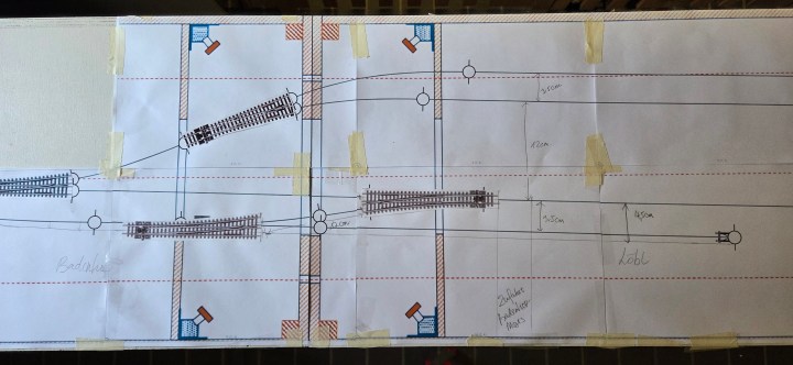
Am anderen Ende musste auch Weiche 14 im Effem-Anschluss um einige Millimeter vom Modulende weg verschoben werden. Abgesehen von diesen Anpassungen passen alle anderen Weichen genau dorthin, wo sie vorgesehen sind.
Die Papierweichen helfen mir aber nicht nur dabei, einen besseren visuellen Eindruck von der gesamten Gleisanordnung auf dem Modul Effem zu bekommen. Gleichzeitig kann ich damit prüfen, was sich später unter der Grundplatte befindet. So lässt sich beispielsweise erkennen, ob eine Weiche mit Querstreben oder anderen Teilen des Modulrahmens kollidiert. Auch die genaue Lage der Stellschwelle und des Herzstücks kann ich bereits bestimmen. Das ist besonders wichtig für die spätere Verdrahtung und die Positionierung von Unterflur-Weichenantrieben wie den MTB-Antrieben oder von manuellen Weichenstellhebeln.
Da ich Flexgleise verwende, ist für mich vor allem eines entscheidend: Die Weichen müssen zuerst an der richtigen Stelle liegen. Sind ihre Positionen und Winkel festgelegt, verbinden die Flexgleise im Grunde nur noch die einzelnen Weichen miteinander.
Diese kleine Übung hat mir wieder einmal gezeigt, warum ich vor dem endgültigen Bau gerne mit solchen „Prototypen“ arbeite. AnyRail liefert mir den Plan – aber erst der 1:1-Aufbau auf dem tatsächlichen Modul zeigt mir, ob dieser Plan in der Praxis wirklich funktioniert.


One thought on “Verden-Walsroder Eisenbahn (VWE): Paper Turnouts for Fit-for-Purpose Tests”