
Note: This will be a series of posts relating to my first FREMO N-scale module based on N-RE (Spur N Regelspur Europa; N-scale Standard Gauge Europe) standards. I hope you will enjoy reading about the background of a private branch line (private Nebenbahn) located near the river Aller in Lower Saxony (Niedersachsen), as well as my planning, construction, and eventually the operation of the FREMO module.
Deutsche Version weiter unten, hier klicken.
Givens and Druthers
North American modellers will be familiar with the term “Givens and Druthers”, popularised by the late John Armstrong. “Givens” are the hard parameters that define a model railroad module or layout. These are constraints that simply cannot be breached: the dimensions of a room, the position of columns, transport limitations, or operational requirements such as minimum walk-around space. “Druthers”, on the other hand, are the things we would like to include on the layout if circumstances allow.
In earlier posts, I shared the “druthers” — or design principles — behind my FREMO module, Verden-Walsroder Eisenbahn (VWE). This post looks at the “givens” that actually shape the project.
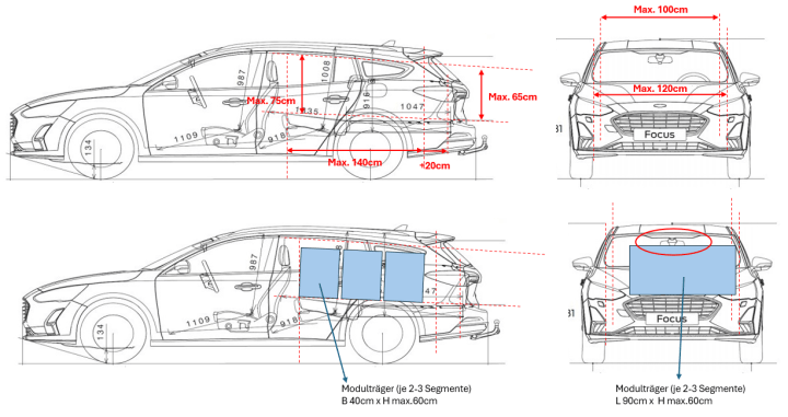
One thing that quickly became clear is that FREMO meets are rarely held near city centres, and many participants willingly travel hundreds of kilometres to attend. That says a lot about the passion and camaraderie within the FREMO community. For me, though, the biggest practical limitation is much simpler: my Ford Focus combi. The measurements shown below in red define my transport “givens”. Once space is reserved for accessories, transport boxes, and a small amount of luggage, the maximum dimensions of my segments are effectively fixed.
In practical terms, I can transport up to nine segments to a meet, although six is probably the more realistic number.
So what does that actually mean operationally? Six segments allows me to bring either the Effem (Eitze) module, which consists of five segments, or the Verden (Aller) Süd/Klbf module, which consists of four segments. Transporting all nine segments means I can bring both modules together.

Module Dimensions
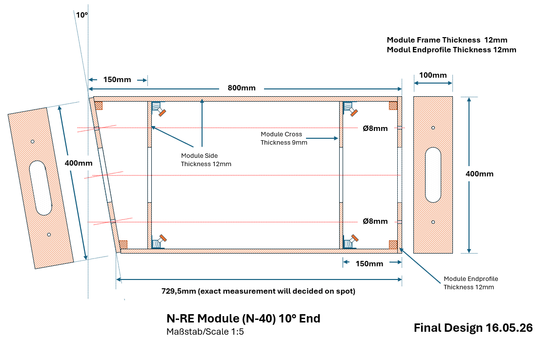
The FREMO N-RE standard defines a module end profile of 400 × 100 mm, with a rail height of 1300 mm (1.3 m) from the floor. For single-track modules, the track centreline is positioned 200 mm from either side of the module. On double-track modules, the centreline of the first track remains at 200 mm, with 25 mm spacing between adjacent tracks.
For harbour and industrial modules, we also use a derivative of the N-RE standard that allows the track centreline to be positioned just 80 mm from the edge of the module. However, these modules are restricted to a single track only.
Between the standardised end profiles, modellers are otherwise free to arrange their track layouts as they wish, provided the minimum curve radii are respected.
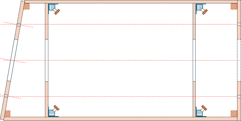
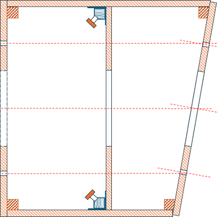
For my own standard modules, I settled on dimensions of 800 × 400 mm. The dotted red lines shown below serve as alignment guides for positioning the track centreline consistently during construction.
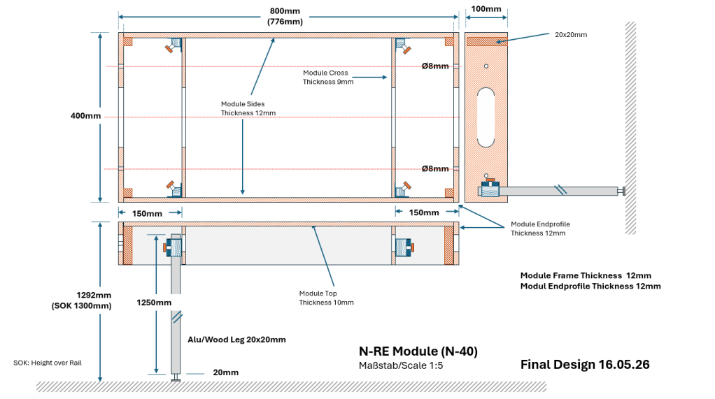
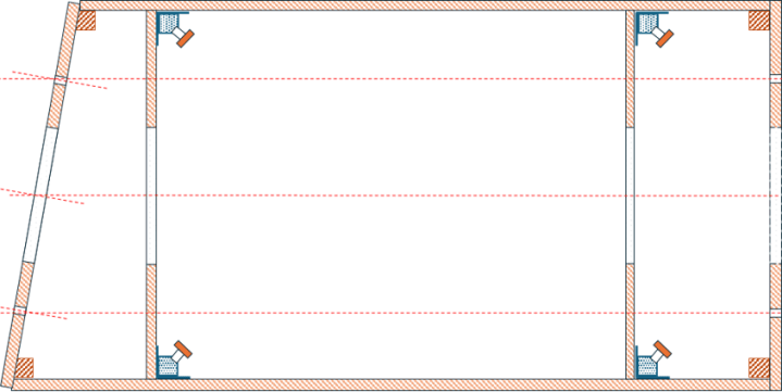
I also developed a module design with a 10% angled end on one side. This gives me a little more flexibility when arranging the modules at meets and helps avoid layouts becoming too visually rigid or parallel.

Variations of Module Design
In the end, I found that I needed five different variations to cover the full range of modules required for the layout.
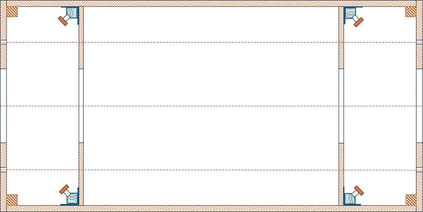
Type A1: Straight Module 800 x 400mm
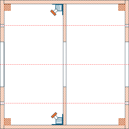
Type A2: Straight Module 400 x 400mm
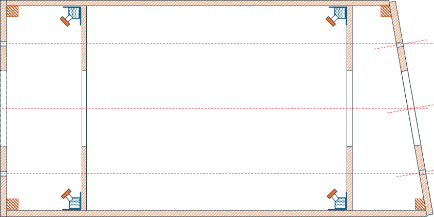
Type B: 10° End 800 x 400mm
Type C1: 10° End 800 x 400mm
Type C2: 10° End 400 x 400mm
DEUTSCHE VERSION
Verden-Walsroder Eisenbahn (VWE): Modulzeichnungen finalisiert
Givens and Druthers
Nordamerikanische Modellbahner kennen vermutlich den Begriff „Givens and Druthers“, geprägt vom inzwischen verstorbenen John Armstrong. Mit „Givens“ sind die festen Rahmenbedingungen gemeint, die den Bau einer Modellbahnanlage oder eines Moduls bestimmen. Dazu gehören Dinge, die sich schlicht nicht ändern lassen: Raumabmessungen, Stützen im Raum, Transportmöglichkeiten oder auch betriebliche Anforderungen wie ausreichend Platz zum Umlaufen der Anlage. „Druthers“ dagegen sind die Dinge, die man gerne umsetzen würde — sofern die Rahmenbedingungen es zulassen.
In früheren Beiträgen habe ich bereits meine „Druthers“, also die gestalterischen Grundprinzipien meines FREMO-Moduls Verden-Walsroder Eisenbahn (VWE), vorgestellt. In diesem Beitrag geht es nun um die „Givens“, die das Projekt tatsächlich begrenzen und formen.
Relativ schnell wurde mir klar, dass FREMO-Treffen meist nicht gerade in Innenstadtnähe stattfinden und viele Teilnehmer bereit sind, mehrere hundert Kilometer für ein Treffen zu fahren. Das sagt eigentlich schon alles über die Leidenschaft und Kameradschaft innerhalb der FREMO-Gemeinschaft aus. Meine größte praktische Einschränkung ist allerdings deutlich profaner: mein Ford Focus Kombi. Die unten rot eingezeichneten Maße definieren meine Transport-„Givens“. Sobald Platz für Zubehör, Transportkisten und etwas Gepäck eingeplant wird, ergeben sich daraus automatisch die maximal möglichen Segmentabmessungen.
Praktisch bedeutet das: Ich kann maximal neun Segmente zu einem Treffen transportieren, realistisch sind aber eher sechs.
Und was bedeutet das betrieblich? Mit sechs Segmenten kann ich entweder das Modul Effem (Eitze) mit seinen fünf Segmenten oder das Modul Verden (Aller) Süd/Klbf mit vier Segmenten mitnehmen. Mit allen neun Segmenten lassen sich beide Module gemeinsam transportieren.
Modulabmessungen
Der FREMO-N-RE-Standard definiert ein Modul-Endprofil von 400 × 100 mm bei einer Schienenoberkante von 1300 mm über dem Fußboden. Bei eingleisigen Modulen liegt die Gleismitte jeweils 200 mm von der Modulseite entfernt. Bei zweigleisigen Modulen bleibt die erste Gleismitte ebenfalls bei 200 mm, der Gleisabstand beträgt zusätzlich 25 mm.
Für Hafen- und Industriemodule verwenden wir außerdem eine abgeleitete Variante des N-RE-Standards, bei der die Gleismitte nur 80 mm von der Modulkante entfernt liegen darf. Solche Module sind allerdings ausschließlich eingleisig zulässig.
Innerhalb dieser standardisierten Endprofile sind die Modellbahner ansonsten frei in der Gleisgestaltung — solange die festgelegten Mindestradien eingehalten werden.
Für meine Standardmodule habe ich mich schließlich für ein Maß von 800 × 400 mm entschieden. Die unten eingezeichneten roten gestrichelten Linien dienen dabei als Orientierungshilfe, um die Gleismitte beim Bau sauber auszurichten.

Zusätzlich habe ich noch eine Modulvariante mit einem um 10 % abgeschrägten Ende entwickelt. Das sorgt bei Arrangements auf Treffen für etwas mehr Flexibilität und verhindert, dass die Modulstrecken zu starr oder zu parallel wirken.
Varianten des Moduldesigns
Am Ende stellte sich heraus, dass ich insgesamt fünf verschiedene Modulvarianten benötige, um alle geplanten Betriebsstellen und Streckenabschnitte umsetzen zu können.
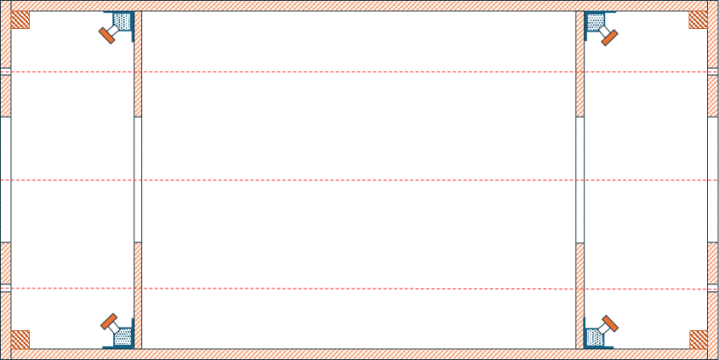
Typ A1: Gerades Modul 800 × 400 mm
Typ A2: Gerades Modul 400 × 400 mm
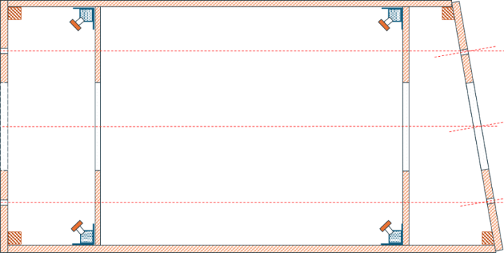
Typ B: Modul mit 10°-Abschluss 800 × 400 mm
Typ C1: Eckmodul mit 10°-Abschluss 800 × 400 mm
Typ C2: Eckmodul mit 10°-Abschluss 400 × 400 mm
