
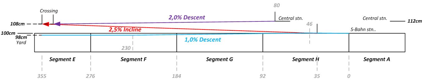
For the last 2 weeks, I had not been seriously working on my layout, for the fact that I had other personal commitments to attend to. During their period, I allowed my layout to “take a rest” and “absorb some sun and humidity”. I think it is important to allow the wood to so-call “breath and adjust to the new environment”. As my friend and fellow N-scale modeller from UK said “that once you have cut your wood I wouldn’t leave it unsupported or leaning on anything. Try and keep it on as flat a surface as you can. Wood has a mind of its own and I hate bent timber.” True, some of the plywood did bent significantly. I had to put some weight on top to push it down. Thank God, it did come down flat or at least did not bend significantly anymore.
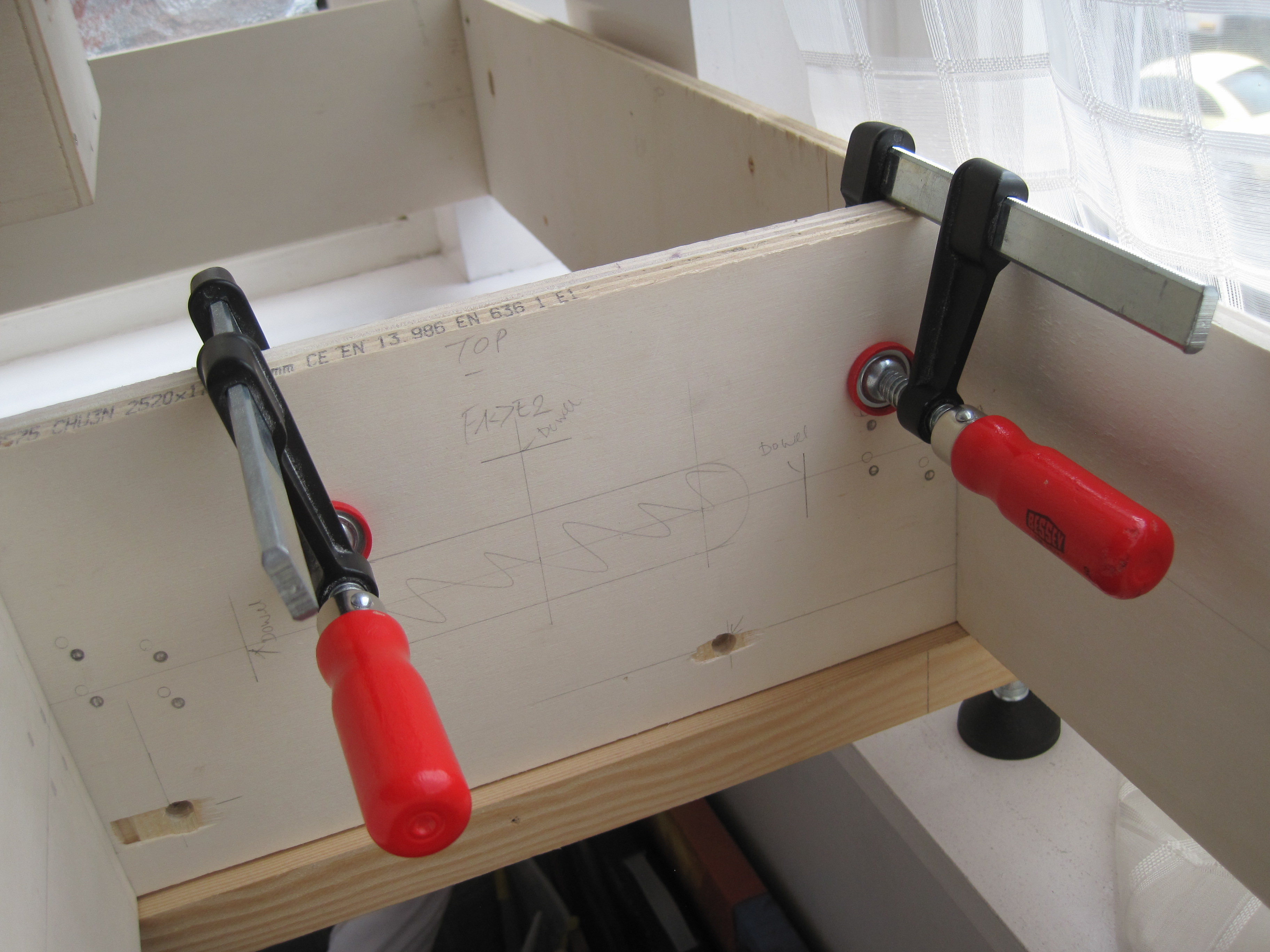
So the 2 weeks allowed me to observe the wood and checked on parts that were uneven. A little readjustment to end profiles to make sure they were square and aligned, screw holes were enlarged slightly to ensure that the modules fitted together. I clamped the end profiles after aligning them again and drilled the holes.
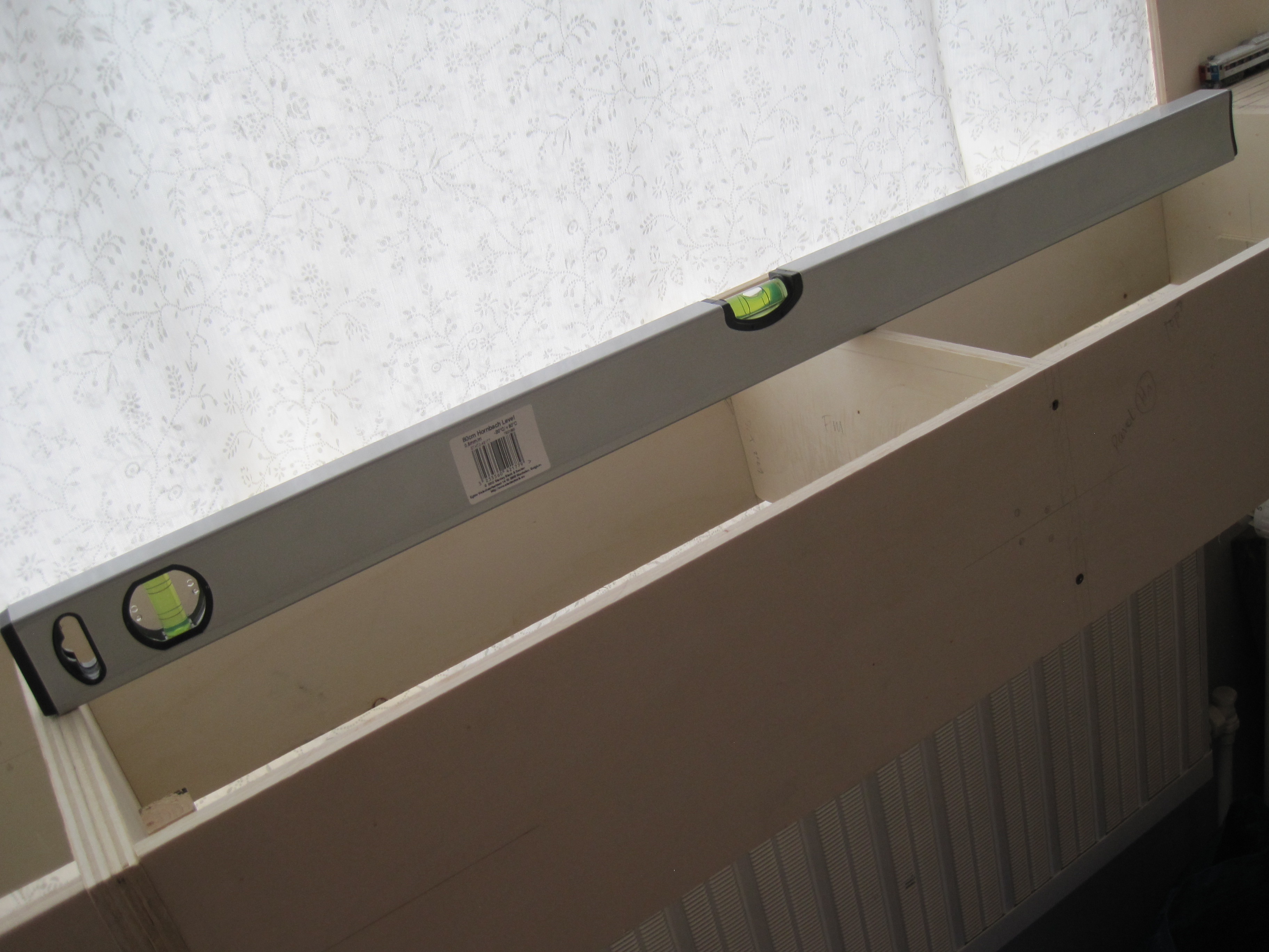
After all the end profiles were aligned, I used the water level to check the vertical and horizontal levelness of each module and from Segment A to Segment E and back. Here was where the adjustable legs came in handy.
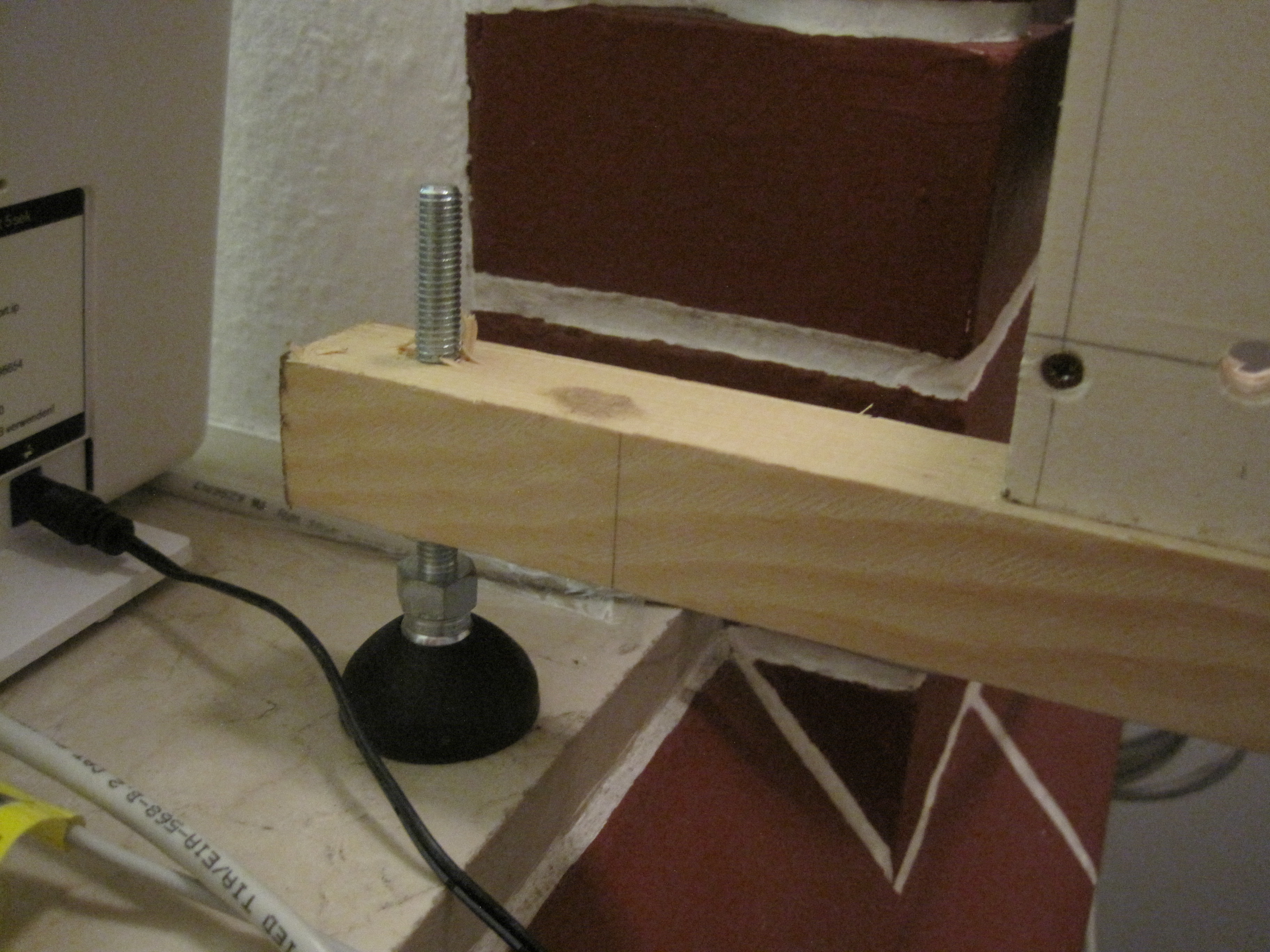
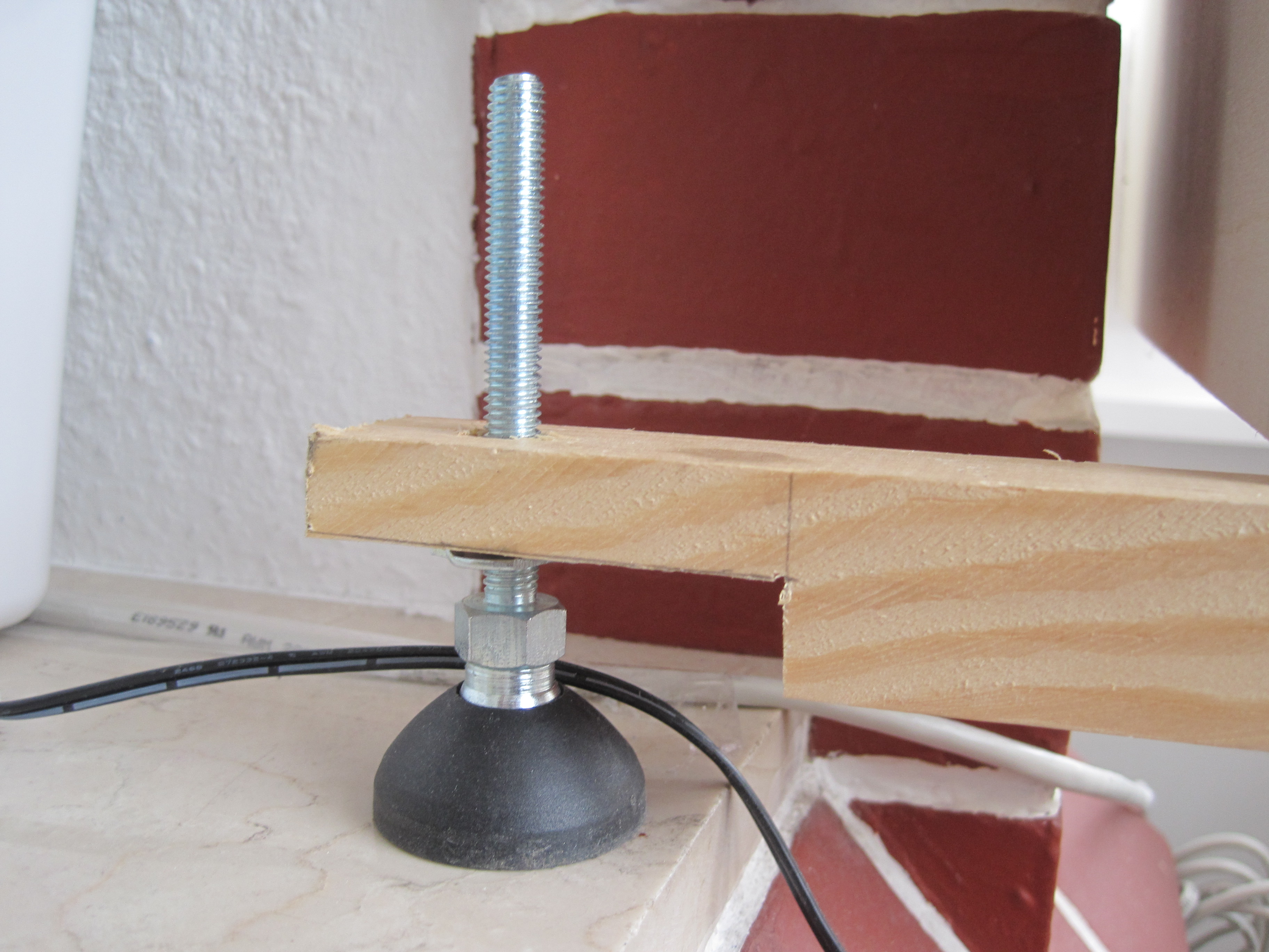
At Segment E, the cross-bar supported the front panel of the module with two adjustable legs at each end. After some trials, I found the cross-bar was too high. Thus, I removed about 1.5cm from each end and lowered the bar.

Now, all 5 segments are ready for track laying.
In my previous post, I showed how I drew the tracks using Atlas flex tracks. I stopped at end of Segment H. This week, I continued with Segment G. Tracks from mid-point of Segment H will start to climb 2.5% towards Segment E.
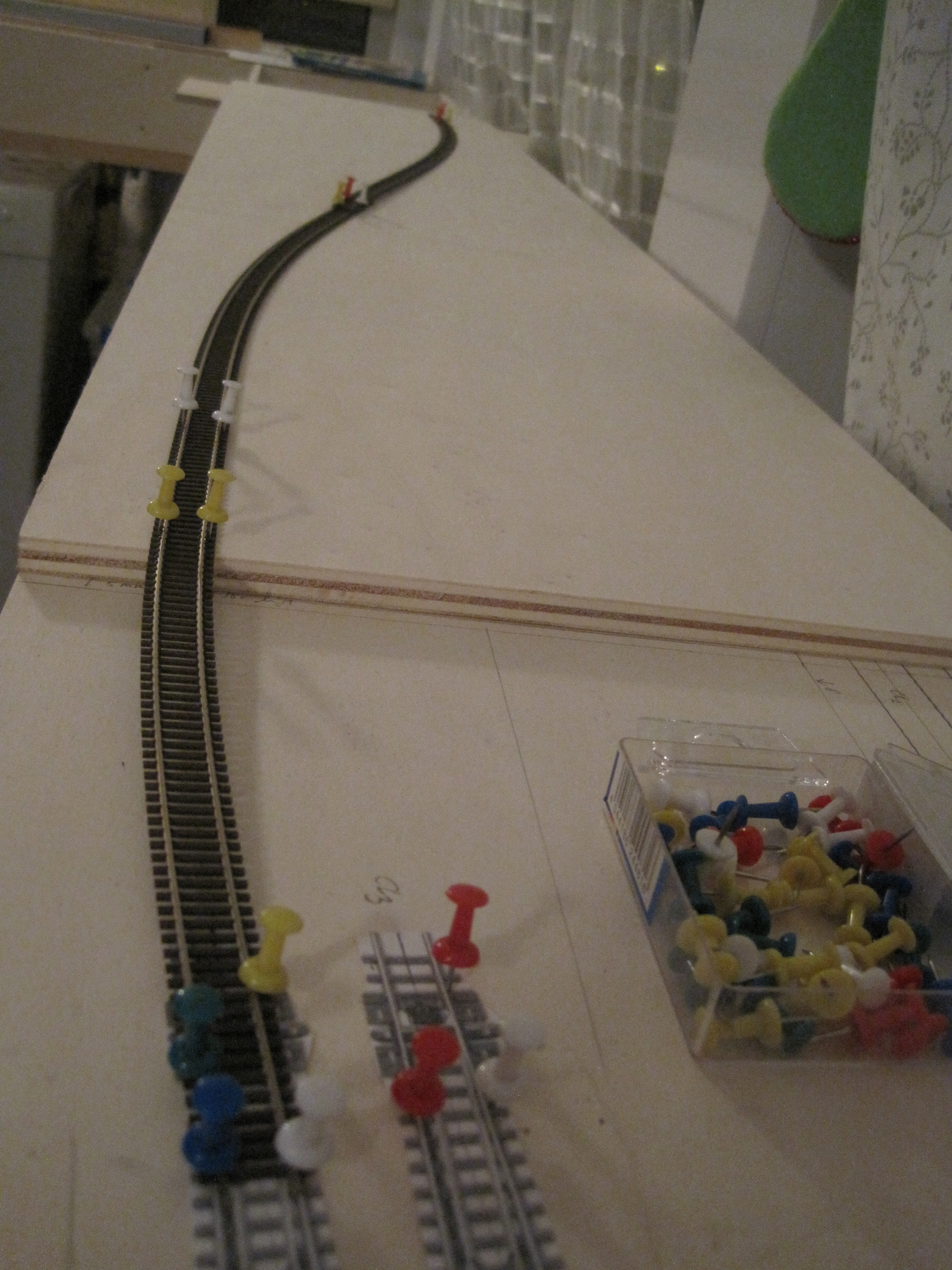

I started by laying and shaping the first track on the left. Using track laying tools (below), I adjusted the second track on the right with a 30mm track spacing. I slid the tools as I moved along and placed pins at strategic locations to maintain the shape of the curve while maintaining 3omm track spacing.

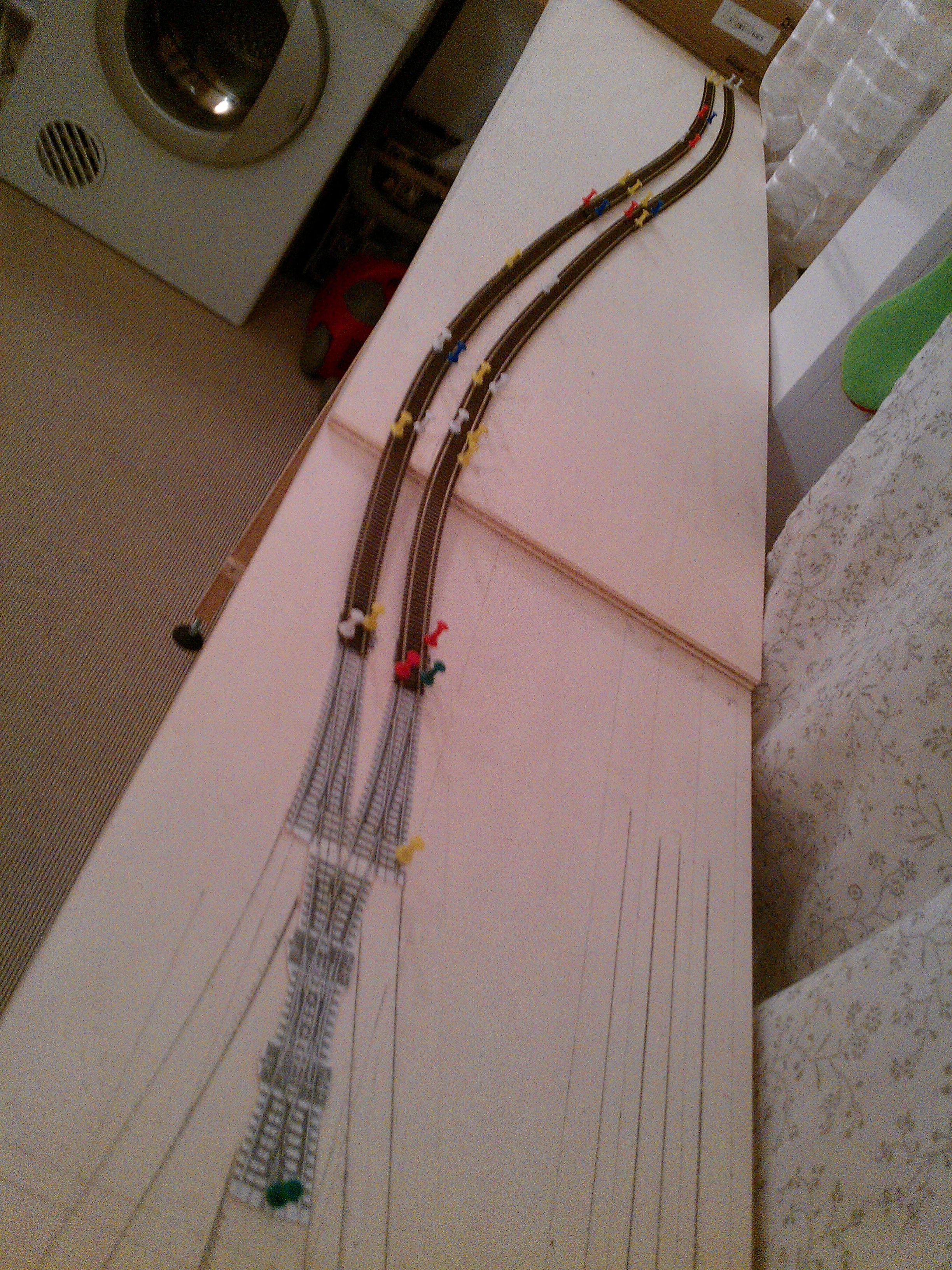


I am pleased with the optical look of the these tracks. Using a geometric compass, I drew the outlines of the track boundary so that I have about 8cm permanent right of ways. The needle traced the tracks while the lead drew the track boundary lines. The track boundaries would be the guidelines for me to cut with a jigsaw.


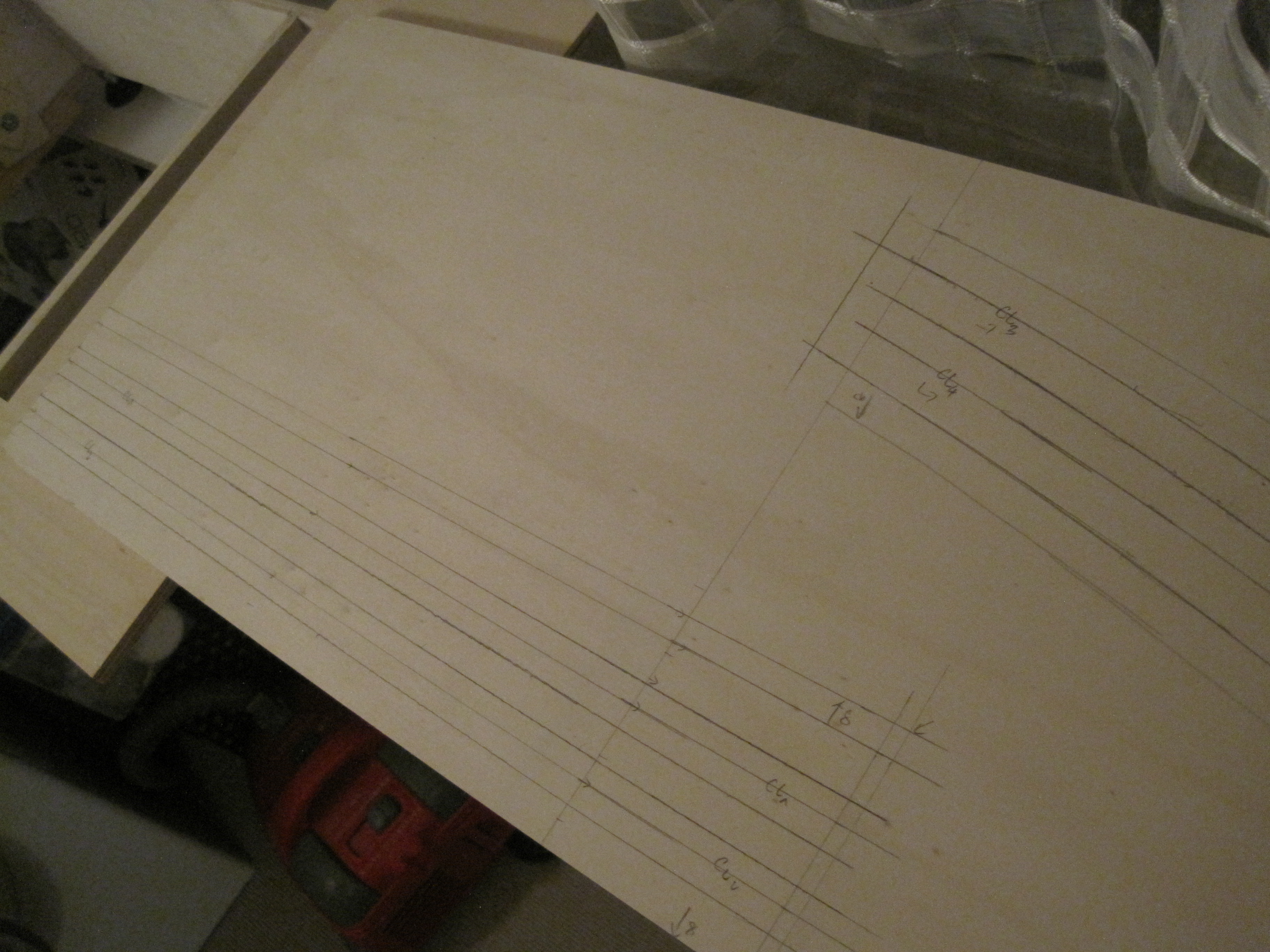
So, the work for this weekend was lined up. There would be lots of cutting and adjusting the appropriate heights. Once the sub-roadbeds are done, the track laying could begin – starting with cork laying and then the tracks.

really starting to take shape! out of interest how much weight is being held on picture 4? you might put a triangular wedge in to add strength?
My guess is it will take on about 30kg. The cross-bar in front and extra adjustable legs at the back will support this module – https://german160.files.wordpress.com/2014/03/img_6411.jpg – which holds 6 staging tracks at the bottom level and a complex crossing at the top – https://german160.files.wordpress.com/2013/11/img_5213.jpg.
I have not decided the landscape at the top level. I guess it should be able to hold the weight. I have tested with all my power tools – Dremel and Bosch and other tool boxes on top for last few days. I will test again with my new portable workshop to see if the corners hold.
It was a really interesting read from your Build #01 to Build #08 and the interludes in between. Looking forward to your Build #09 and onwards. 😉
Thanks Sabri. Glad you enjoy reading them as much as I enjoy planning, building and blogging abt them.
Btw, could you intro a bit abt yourself and your model modelling interests?